
Maintenance
Important information

Only trained and qualified staff is authorized to perform maintenance operations.
A manual mode can be used on the machine if the cabin controls are not working, under the condition that there is a clear view from the manual control station.
You can do so by using the hydraulic levers left with the PK-608 documentation. These levers can be installed directly on the hydraulic valve and moved like handles in order to move all functions, as long as the hydraulic pump is running.
Before performing any electrical arc welding, it is important to link the battery ground to the chassis ground. Also disconnect the positive cable from the battery and disconnect the PK311 PLC cable.
A fully charge battery produces a gas mix of oxygen and hydrogen that can be explosive if heated. While performing welding near the battery, make sure to remove and store away the battery in a ventilated area away from the welding equipment. Apply the same safety procedure for grinding.
After sales and service Packmat Equipment
Phone: 819-479-4972
360 Séminaire N. street – St-Jean sur Richelieu, QC, Canada
Parts, service and warranty
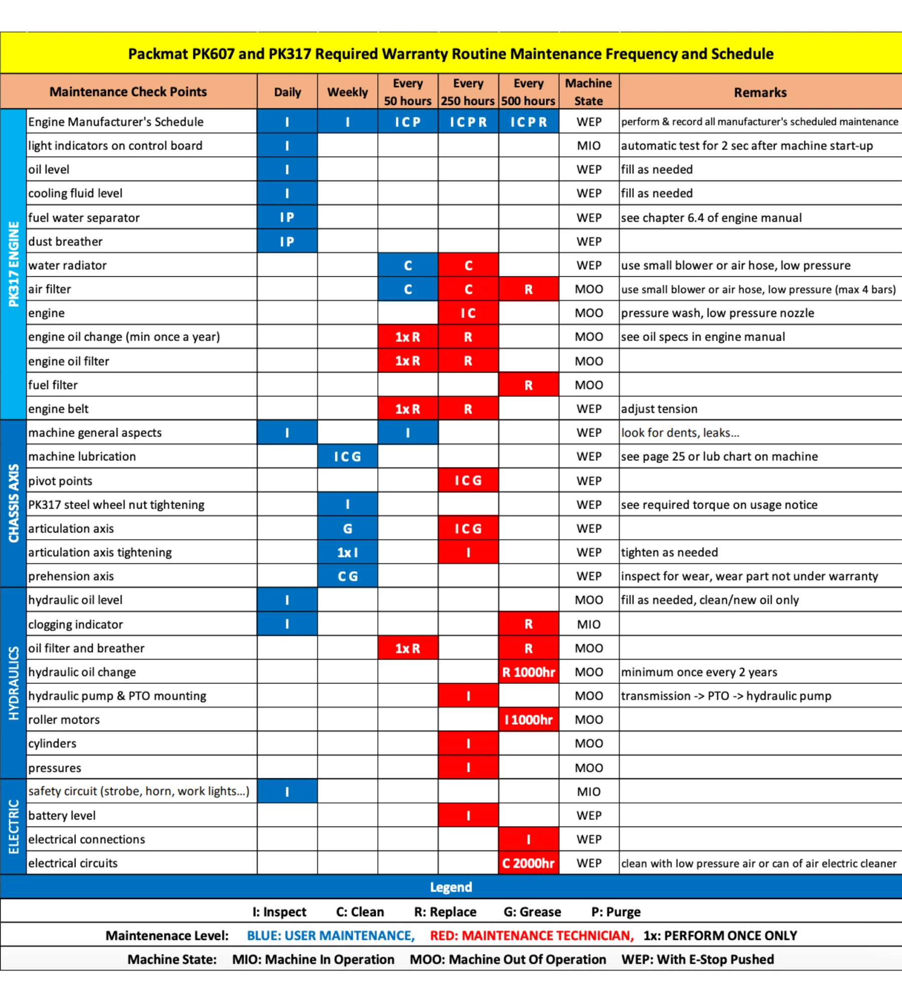
Preventive maintenance plan
Note that some models, like the PK-608, do not have any thermal engine.
General maintenance
The mechanical parts do not require any particular maintenance besides lubrication. The mechanical articulations are mounted on steel rings equipped with grease zerks and require lubrication weekly.
During maintenance operations, it is recommended to perform the following operations:
- Pack 2 containers
- Raise arm
- Float
- Make roller spin in both directions
- Stroke limit check
- Check the cylinder bellow
- Check the wear on mechanical stoppers
- Check roller rotation speed: front spin: 15 to 25 rpm
- Check roller rotation speed: front spin: 15 to 25 rpm
- Lower arm time: between 24 and 26 seconds
- Raise arm time between 24 and 26 seconds
- Max unfolding of the arm (roller arm and intermediate arm aligned)
- Check wear on gripping handle on: smaller side to side with the most wear: 400mm (16 inches)
- Check for wear and tears on roller arm
- Check for wear and tears on intermediate arm
- Check inclinable arm
- Visual inspection on chassis
- Check for cracks on cabin
- Check for cracks on glass and plexiglass
- Every 1500 hours, change coupling PK003-PE04-03
Electrical maintenance
During maintenance operations, it is recommended to perform the following operations:
- Make sure the E-Stop is working properly
- Make sure the front working lights are working properly
- Check the filter and engine clogging lights
- Make sure strobe light is working
- Make sure temperature gauge is working
- Check if unfolded arm buzzer is working
- Make sure packer rotation speed is set between 1590 rpm and 1610 rpm.
Hydraulic maintenance
Check the following during maintenance operations:
- Check the clogging filter, clean if needed
- Check the hydraulic oil level
- Check for the proper movement of the flexible arm hoses
- Check if hydraulic connections have leaks
- Check for leaks on the cylinder rods. If there is an internal leak on the arm raise cylinder, rod will go down 6 inches per hour when roller is raised to its max.
- Check that there are no oil leaks on drain
- Check that all rigid lines are well attached
- Check stand-by pressure
- Check relief pressure when roller folded, should between 4600 to 4700 psi
- Check relief pressure when roller unfolded, should between 4600 to 4700 psi
Manual lubrification
Lubrication diagram.

Lubrification system (optional)
If your machine is equipped with the optional automatic lubrication system Twin by Groeneveld, the system will automatically and simultaneously lubricate all connected zerks following a specific cycle time and a specific grease quantity.
The system includes:
- Pump with integrated command unit
- Distribution blocs with dosage units
- Display screen Twin-3 with error codes
CAUTION : even if the machine is equipped with an automatic lubrication system, always check weekly if a hose might be disconnected.
System operation
The system takes charge of all operations. Once turned ON, the pump provides predetermined grease quantity. The display screen Twin-3 will indicate the working status of the system.
Display Twin-3
With button (1), select the desired operating or test mode and reset all errors (see pages 3 to 6). The Twin-3 has a 3 digit display (2). The decimal comma (3) indicates if the the time ris working or in stanby (see page 8). The green LED (4) indicates if the system is actived. The yellow LED (5) indicates if the low grease level is reached. The red LED (6) indicates a malfunction.

- Button
- 3-digit screen
- Decimal point
- System activation LED indicator
- Low-grease LED indicator
- Alarm LED indicator
Pump settings

- Heavy duty cycle: 30
- Normal duty cycle: 90
- Low duty cycle: 120
Legend
3 - Grease metering output
Deported lubrication (optional)
