Maintenance
Daily checks
- Carrier vehicle oil levels.
- Machine hydraulic oil level.
Greasing
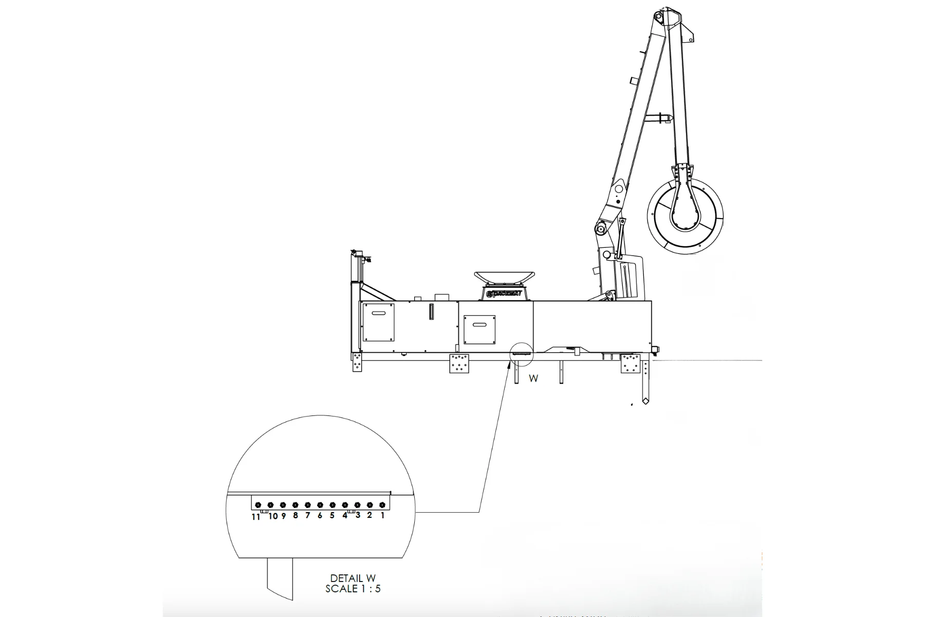
- *Refer to schematic below
Greasing Frequency
- Points 5, 6, 7, 8: Grease weekly or every 100 compactions
- Points 1, 2, 3, 4, 9, 10, 11: Grease monthly or every 300 compactions
Greasing Procedure
- Clean the grease fitting to remove dirt and debris.
- Remove old grease from the joint.
- Apply fresh grease according to the required frequency for each point.
- Confirm grease flow: ensure new grease comes out of the joint to validate proper lubrication.
Disclaimer
- Always stay alert for squeaking or grinding noises. Any unusual sound is a sign that the joint needs greasing.
- If using the side greasing line (refer to schematic below), avoid over-greasing. Excess pressure can damage the greasing line.
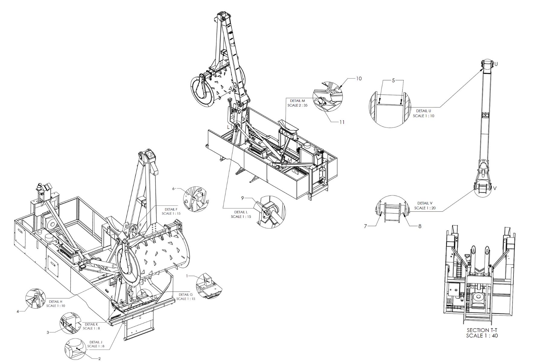
Grease Pivot Joints
- PLANE, lower right frame bearing (#1 )
- PLANE & SECOND ARM, cylinder lower bearing (#2 )
- PLANE, lower left frame bearing (#3 )
- PLANE, left cylinder, upper bearing (# 4)
- PLANE, right cylinder, upper bearing (# 9)
- PLANE, left cylinder, lower bearing (#10 )
- PLANE, right cylinder, lower bearing (# 11)
- PLAN & SECOND ARM, upper left pivot joint (#8 )
- PLAN & SECOND ARM, upper right pivot jount (#7 )
- PLANE & SECOND ARM cylinder upper bearing (#6 )
- SECOND ARM & ROLLER ARM, pivot joint (#5 )
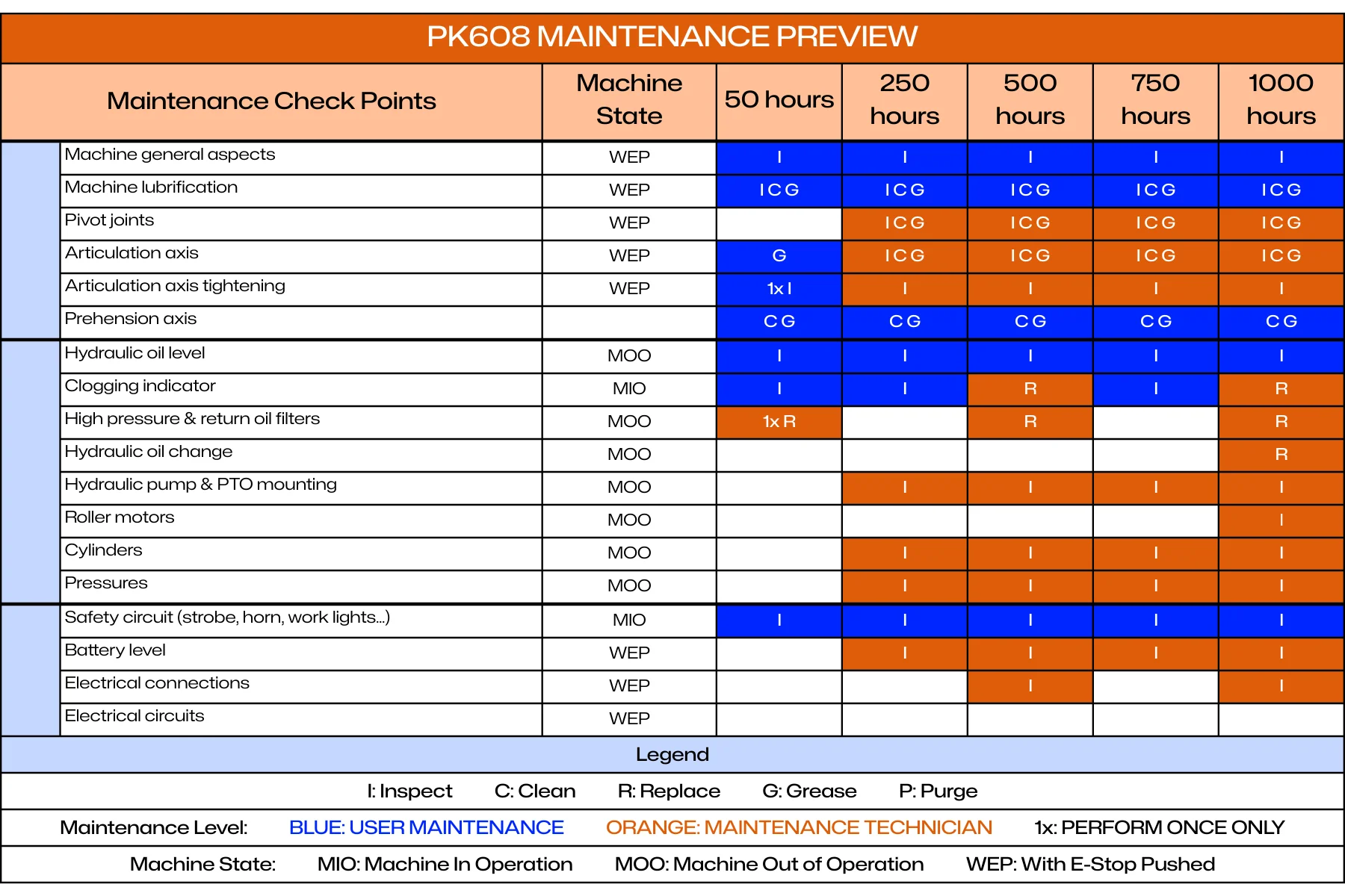
Long-term Maintenance
The maintenance light on the control box illuminates every 250 hours as part of the long-term service schedule. This light will not turn off automatically, even if the required maintenance has been completed. It must be reset manually.
To reset the maintenance light, press and hold the WORK LIGHT button on the joystick for 20 consecutive seconds. The light will turn off once the reset is complete.
Please note that we strongly recommend performing the initial 50-hour service inspection to ensure proper break-in and long-term reliability.
As a reminder, maintenance is required every 250 hours for the lifetime of the machine. All detailed maintenance tasks and intervals are described in the Warranty Manual. Always refer to that manual for full procedures and service requirements.
Parker PLC Remote Diagnostics
The PK608 is equipped with a Parker PLC controller featuring Bluetooth connectivity for remote diagnostics and system monitoring. This section provides procedures for connecting to the PLC and accessing diagnostic information.
Through this interface, users can read input signals from sensors and switches, and monitor output functions to verify circuit integrity. This helps identify damaged or disconnected wires, faulty switches, or sensor issues during troubleshooting.
IQANgo Application Setup
The IQANgo smartphone application allows wireless connection to the Parker PLC for diagnostics, monitoring, and data retrieval.
Application Installation
Download IQANgo:
- Open app store on smartphone (Apple App Store or Google Play Store)
- Search for "IQANgo"
- Download and install the free IQANgo application
- Launch application after installation
Application Overview
IQANgo provides access to PLC functions including:
- System monitoring and diagnostics
- Variable measurement and logging
- Hour meter reading
- System settings viewing
- Log file retrieval
Bluetooth Connection Procedure
Follow this procedure to connect your smartphone to the PK608 Parker PLC via Bluetooth:
Connection Steps
Prepare PK608
- Ensure vehicle engine is running
- Turn PTO switch ON
- Turn PK608 power switch ON
- Verify PLC is powered and operational
Open IQANgo Application
- Launch IQANgo app on smartphone
- Ensure smartphone Bluetooth is enabled
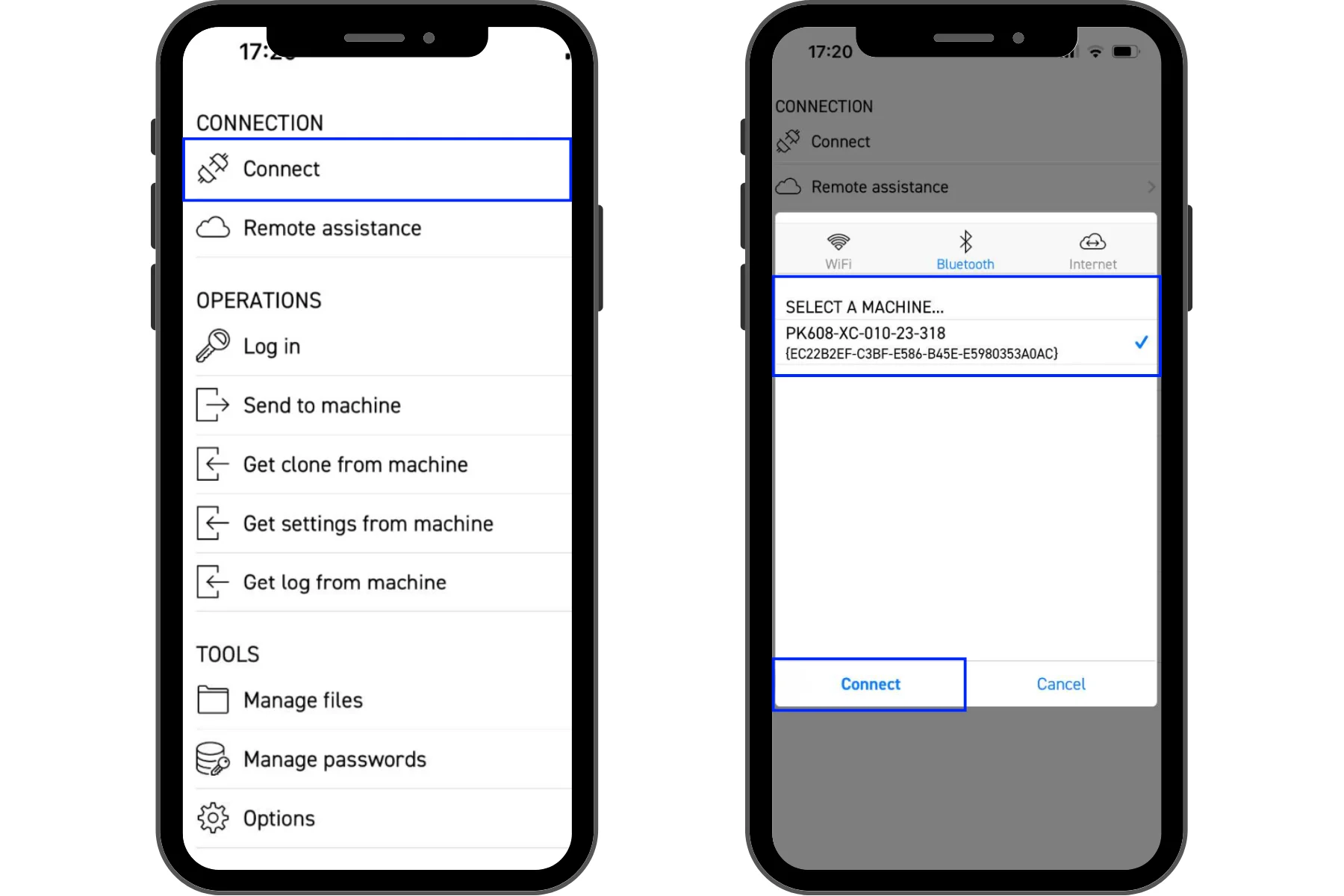
Connect to PLC
- In IQANgo app, tap "CONNECT"
- Select "Bluetooth" tab
- Wait for app to scan for available devices
Select Machine
- From list of available devices, select your PK608 unit
- Device naming format: PK608-XC-010-23-318 (example)
- Tap "Connect"
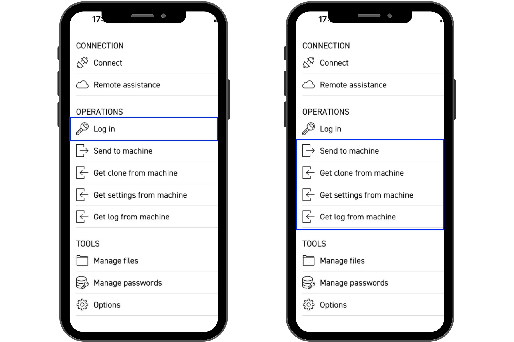
Login to PLC
- Tap "Log in" in the OPERATIONS menu
- Enter login credentials:
- First bluetooth connection with cellphone
- Password : 123456
- In the application IQAN GO Login
- Client :
- Username: Client
- Password : 1234
- Technicien :
- Username: TECH
- Password (2023 units): PK608
- Client :
- First bluetooth connection with cellphone
- Tap "OK" or "Login"
Verify Connection
- Upon successful login, you will have access to PLC functions
- Main menu shows available operations:
- Send to machine
- Get clone from machine
- Get settings from machine
- Get log from machine
You are now connected to the PK608 PLC and can access diagnostic functions.
System Monitoring and Diagnostics
The IQANgo application provides access to real-time system variables for monitoring and diagnostics.
Accessing Measure Groups
Open Measure Function
- From main menu, tap "Measure" button (bottom navigation bar)
- This displays available measure groups
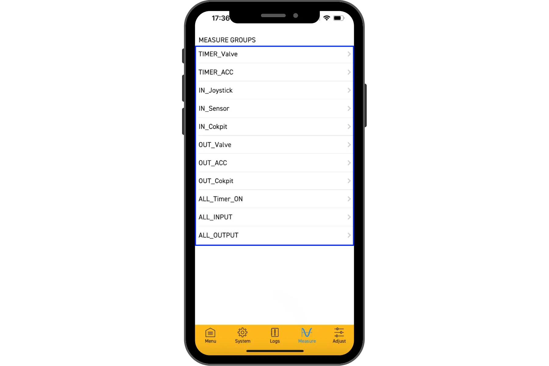
Available Measure Groups
- TIMER_Valve: Valve operation timers
- TIMER_ACC: Accessory timers
- IN_Joystick: Joystick input values
- IN_Sensor: Sensor input values
- IN_Cokpit: Cockpit/cab input values
- OUT_Valve: Valve output values
- OUT_ACC: Accessory output values
- OUT_Cokpit: Cockpit/cab output values
- ALL_Timer_ON: All system timers (including hour meter)
- ALL_INPUT: All system inputs
- ALL_OUTPUT: All system outputs
Select Measure Group
- Tap on desired measure group to view variables
- Variables are displayed with current values
- Values update in real-time
Hour Meter Reading
The PK608 tracks operating hours using the Parker PLC. Follow this procedure to read the hour meter:
Hour Meter Procedure
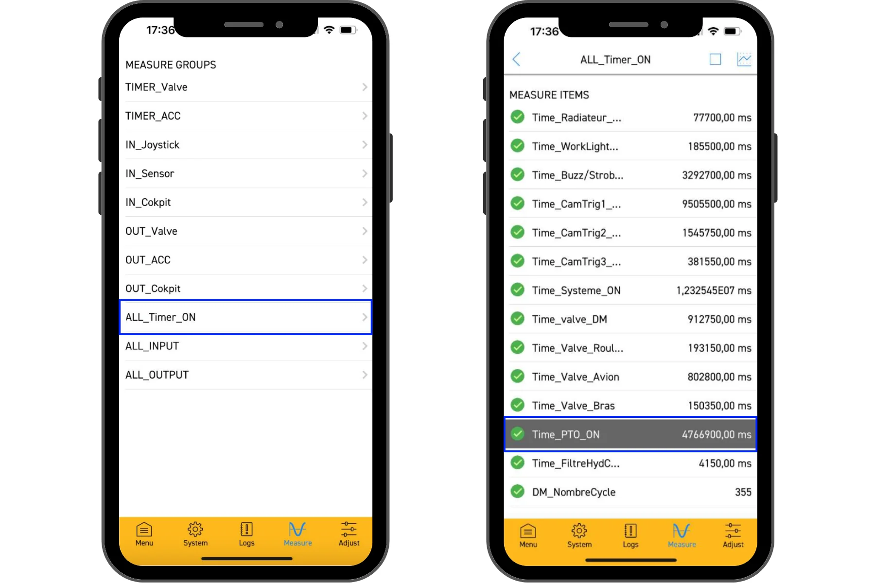
Select Timer Group
- From Measure menu, tap "ALL_Timer_ON"
- This displays all system timers
Locate PTO Hour Meter
- Scroll through timer list to find "Time_PTO_ON"
- This timer tracks total hours with PTO engaged (actual operating hours)
Read Timer Value
- Timer value is displayed in milliseconds
- Note the value (example: 4766900 ms)
Convert to Hours (*if the application shows ms only)
- Divide timer value by 3,600,000 to convert milliseconds to hours
- Formula: Hours = Timer Value (ms) ÷ 3,600,000
- Example: 4,766,900 ms ÷ 3,600,000 = 1.32 hours
Note: Some PLCs may be programmed in different time units. Verify the conversion factor is correct by comparing with known operating hours.
Truck Fuses
Locate the fuse box(s) for the truck, the location should be in the truck manual. We recommend that you keep at least one (1) spare fuse for each fuse in the box.
Packmat Fuses
The Packmat fuses are located in the control panel which is located behind the driver side of the truck cab. The access door is behind the side panel. The door requires the small blue plastic key to open. We recommend that you keep at least one (1) spare fuse for each fuse in the box.
You will also find two additional 30-AMP main fuses located in the battery compartment.
Tools & Supplies
The Packmat is a heavy duty hydraulic machine. You may experience some routine items that will require tools to fix. Some of the items that will require tools to repair, and the suggested tools.
- Loose hydraulic line or fitting → need metric wrenches, open end & adjustable
- Loose screw(s) on the side panels → need flat, Philips, & torx screw drivers
- Loose allen screw → need metric & standard allen wrench set
- Bent limit switch from dumpster debris → pliers & adjustable wrench
- Wire wrapped around roller → need bolt cutters, long handle wire cutters, & hand wire cutters
- Rags → remove excess grease that drips from fittings
- Grease Gun with extra grease cartridges
- Broken hydraulic line → Pirtek is a national mobile hydraulic repair company, www.pirtekusa.com
Packmat Grease Fittings
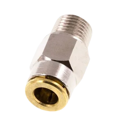
Push-in fitting used on back of grease manifold on side of Packmat.
6mm x M 10 x 1 (conical) Push-in Fitting with Male Threads Brass NBRHigh Pressure [2 Pieces]
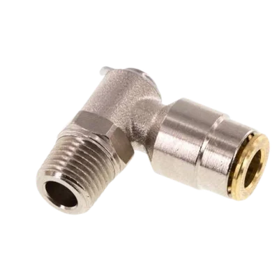
90 degree fitting used at the pivot points on the Packmat.
6mm x M 10 x 1 (conical) 90deg Elbow Push-in Fitting with Male Threads Brass NBR RotatableHigh Pressure